
7680×4320 8K | High-Refresh Esports Panels | Flexible Card-Based Configuration
Card-based design with 4 signal card slots plus 1 dedicated control card slot. Optional LVDS / LVDS-P / V-by-One / eDP cards can be combined in parallel for up to 7680×4320 output, easily driving 8K panels and all kinds of high-refresh notebook and esports displays. Performance rivals imported instruments at a significantly better price. Flicker (VCOM) adjustment supported; with the 7-inch touchscreen RMT-221 control box, the entire test requires only 3 buttons.
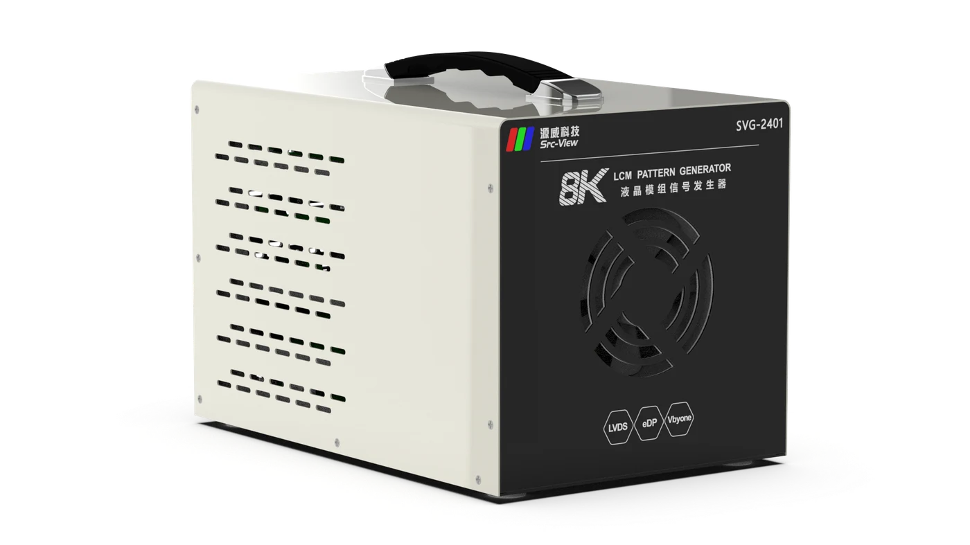
An 8K card-based LCM pattern test instrument — performance rivaling imports, flexible configuration, covering TV, monitor and notebook production lines
4 V-by-One cards in parallel deliver 64 lanes, or 2 eDP cards deliver 16 lanes, for up to 7680×4320@120Hz; a single V-by-One card supports 3840×2160@144Hz.
4 signal card slots plus 1 dedicated control card slot. LVDS / LVDS-P / V-by-One / eDP cards are optional and plug-and-play; simply add cards later as panel types change.
eDP rates up to 8.1Gbps; the LVDS-P high-refresh card supports 1920×1080@360Hz — easily driving all kinds of high-refresh notebook and esports displays.
Supports pattern testing of Samsung, LG and other OLED modules; provides dedicated OLED signals including VDD, ELVDD, AC_DET and ELVDD_EN, with OLED Power On Sequence and Power Off Sequence control.
I2C-based VCOM voltage adjustment; the control box offers +5 / -5 / +1 / -1 four-key fine-tuning, and the "Save" key writes the value to the panel T-CON board memory in one step.
All output signals are protected; panel power and backlight power feature configurable over-voltage, under-voltage, over-current and no-load protection; VCC / VBL support soft start to suppress inrush current at power-on.
The standard RMT-221 control box features a 7-inch capacitive touchscreen with full touch operation, a bilingual Chinese/English interface and dual operator/administrator permissions; an IR remote control can also switch signals and patterns.
Editable RGB solid colors, card-algorithm built-in patterns, external BMP images from SD card, and scrolling bar patterns; frame-lock supported with independently set duration per frame and auto/manual switching.
Ready instantly at power-on — no boot wait. Store 99 sets of module parameters; switching lines or panels means just switching a parameter number. RS-232 commands let AOI equipment set parameters, switch signals, change patterns and read status.
Configure by panel, expand on demand — buy only what you need and save costs; panel upgrades only require additional cards
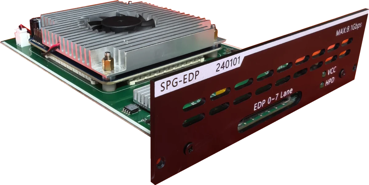
8-lane eDP at 1.62 / 2.7 / 5.4 / 8.1Gbps, 6 / 8 / 10-bit; a single card reaches 7680×4320@60Hz, and 2 cards in parallel (16 lanes) reach 8K@120Hz. Ideal for notebook panels, esports displays and 8K panel testing.
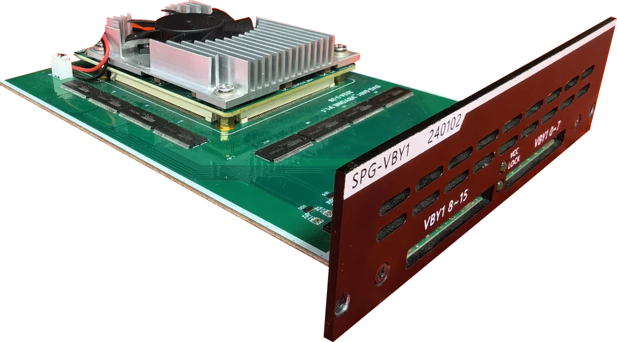
16-lane V-by-One at 3.75Gbps/lane, 8 / 10-bit, 1 / 2 / 4 division; a single card reaches 3840×2160@144Hz, and 4 cards in parallel (64 lanes) reach 7680×4320@144Hz. Ideal for TV panels and large-size module testing.
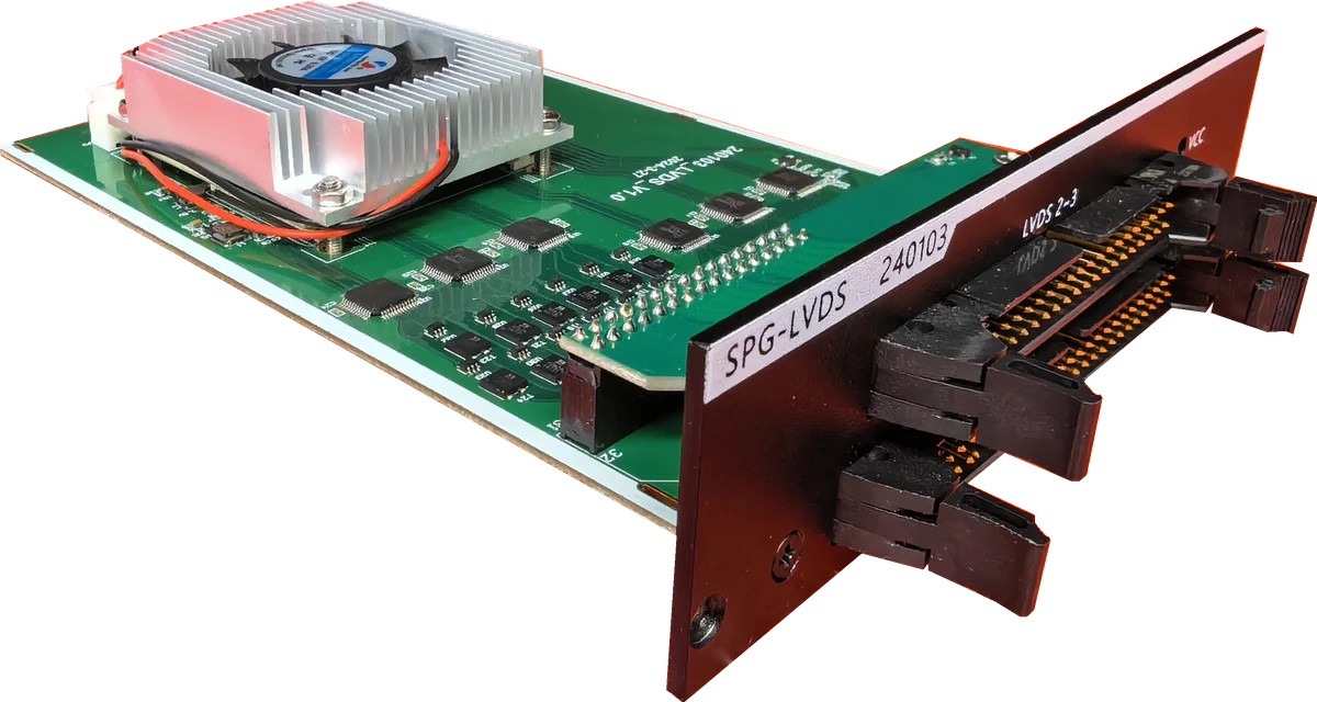
4-channel LVDS at 150MHz/channel, 6 / 8 / 10-bit, JEIDA / VESA; up to 1920×1080@240Hz; can drive two 2-channel panels or four 1-channel panels simultaneously, doubling line efficiency.
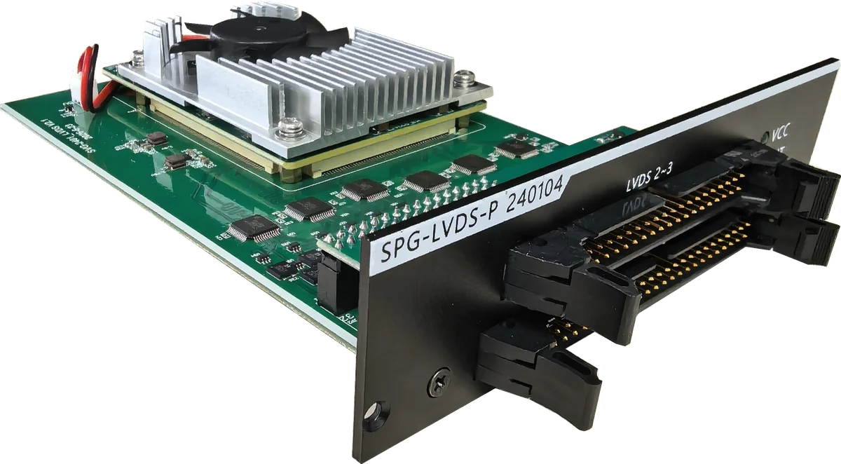
4-channel LVDS at 200MHz/channel, 6 / 8 / 10-bit, JEIDA / VESA; up to 1920×1080@360Hz — purpose-built for high-refresh notebook panels and esports displays.
Detailed electrical and functional parameters meeting 8K and high-refresh panel production-line testing needs
| eDP Card 240101 · Optional |
1 / 2 / 4 / 8 / 16 / 32 Lane 1.62 / 2.7 / 5.4 / 8.1Gbps 6bit / 8bit / 10bit 8-lane, up to 7680×4320@60Hz 16-lane (2 cards), up to 7680×4320@120Hz |
|---|---|
| V-by-One Card 240102 · Optional |
1 / 2 / 4 / 8 / 16 / 32 / 64 Lane Division 1 / 2 / 4 8bit / 10bit 3.75Gbps/Lane 16-lane, up to 3840×2160@144Hz 64-lane (4 cards), up to 7680×4320@144Hz |
| LVDS Card 240103 · Optional |
Single / Dual / Quad Channel Division 1 / 2 / 4 6bit / 8bit / 10bit JEIDA / VESA 150MHz/channel Up to 1920×1080@240Hz Drives two 2-channel or four 1-channel panels simultaneously |
| LVDS-P Card 240104 · Optional |
Single / Dual / Quad Channel Division 1 / 2 / 4 6bit / 8bit / 10bit JEIDA / VESA 200MHz/channel Up to 1920×1080@360Hz Drives two 2-channel or four 1-channel panels simultaneously |
| Flicker Adjustment | I2C-based VCOM voltage adjustment (customer provides the I2C protocol for VCOM adjustment); the VCOM value can be written to the panel’s non-volatile memory |
| Power Signals | Panel power VCC: 3.3V–15V programmable (measurement accuracy 5mV); current 12V/10A, 3.3–5V/3A, other voltages 5A (accuracy 5mA); over-voltage / under-voltage / over-current / no-load protection; soft start suppresses power-on inrush current |
| Backlight Signals | Backlight power VBL: 12V–24V output (accuracy 5mV), max 5A (accuracy 5mA), external constant-current module available (optional); BL_ADJ level adjustable 0.8V–3.9V, frequency 10Hz–20KHz, duty cycle 0–100%; BL_ONOFF level adjustable 0.8V–3.9V; soft start supported |
| Test Patterns | Editable RGB solid-color patterns, card-algorithm built-in patterns, external BMP patterns from SD card, and scrolling bar patterns; frame-lock with independently set duration per frame; auto / manual switching |
| Cursor Positioning | Overlay a cursor on test patterns with configurable coordinates |
| Power Sequencing | Controlled items: LVDSVCC, BLVCC, LVDS / V-by-One / eDP signals, control outputs; interval 5mS–500mS, accuracy 5mS |
| Storage | SD card (FAT32, max 32GB) stores module parameter files and test images; 99 preset module parameter sets, up to 32 test patterns each; parameters can be downloaded via PC serial port or transferred between two units |
| Unit Specifications | Main unit: 213 × 290 × 190 mm, approx. 3.96 kg (without cards); control box: 195 × 180 × 38 mm, approx. 0.95 kg; input 90–132VAC / 180–264VAC (bottom switch), rated 350W; operating temperature +5°C to +45°C |
| Operation | RMT-221 split-type control box (standard), 7-inch capacitive touchscreen, bilingual Chinese/English, operator/administrator dual permissions; testing requires only 3 buttons; IR remote control and RS-232 AOI command integration also supported |
| Standard Accessories | Main unit, RMT-221 control box, SPG-MAIN 240100 control card (with backlight driver), national-standard 3-pin power cord; signal cards (eDP / V-by-One / LVDS / LVDS-P), cables and adapter boards are optional |
Main unit views, card slots and RMT-221 control box layout at a glance
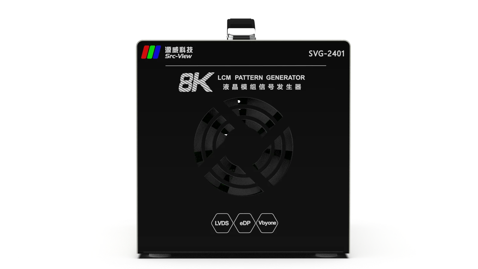
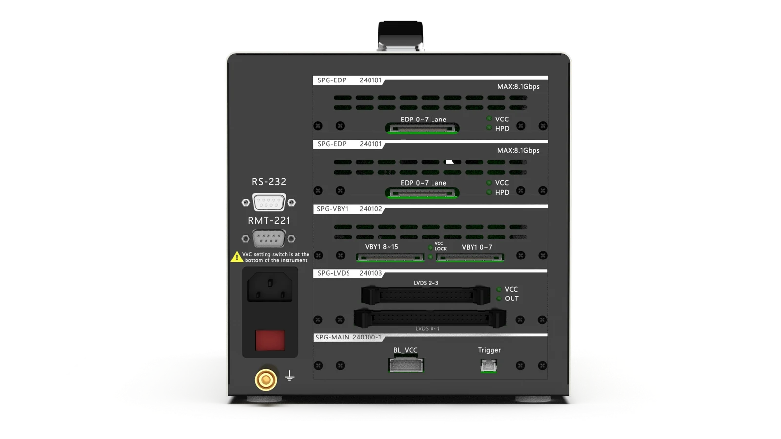
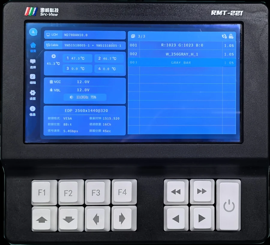
7-inch capacitive touchscreen with full-touch UI in Chinese and English; the main screen shows module parameters, cable, card temperature, VCC / VBL voltage & current and signal format in real time. The power button controls the signal on/off; the previous / next button switches test patterns, with F1–F4 shortcut function keys; frequently used keys are all mechanical keys rated for millions of presses — built to last.
Complete pattern testing in a few simple steps
Covering grayscale, color bar, checkerboard, flicker, crosstalk and other common production-line test screens
RGB solid / built-in algorithm / BMP / scrolling bar
BMP files on the SD card can be used directly
Combine test screens as needed
Switch lines/panels by parameter number only
Independent duration per test frame





























A full comparison of pattern-testing solutions for LCM production lines — professional instruments win across the board
| Item | SVG-2401 Professional Signal Generator | Ordinary Motherboard |
|---|---|---|
| Versatility | ✓Purpose-built for LCM and T-CON production-line pattern testing; card-based structure with optional cards, compatible with LVDS / V-by-One / eDP panels, up to 8K | ✗One motherboard only drives its matching panel — changing glass means changing the board |
| Reliability | ✓All interface signals have protection circuits; T-CON power features over-voltage, under-voltage, over-current and no-load protection | ✗No protection — easily damaged |
| Efficiency | ✓Instant on at power-up, highly efficient | ✗Must wait for the motherboard to fully boot; some boot very slowly |
| Operability | ✓Signal on/off and pattern switching with just 3 buttons | ✗Must switch to the USB channel via remote or buttons first, then control USB image playback |
| Cost-Effectiveness | ✓Designed service life of 5–10 years — better long-term value | ✗Frequent damage or even scrapping — higher overall cost |
| Special Requirements | ✓Independently developed — customization available for special panel-inspection processes | ✗Cannot be met |
| Industry Trend | ✓Major brand LCM manufacturers all use professional instruments for pattern testing | — |
| Success Stories | ✓Wistron, Innolux, AUO, Panda, BOE, TCL CSOT | — |
The Common Choice of Many Leading LCM Manufacturers






Quick ways to locate pattern-testing issues
The SVG-2401 is our flagship in-production model. For selection consulting, card configuration plans or sample demos, feel free to contact us anytime.
A high-tech enterprise dedicated to R&D and production of test equipment and system products — a professional test equipment provider and service partner for electronics manufacturers.