
16-Lane V-by-One | 4-Channel LVDS | 8-Lane eDP | Flicker Adjustment
One instrument integrates 16-lane V-by-One, 4-channel LVDS and 8-lane eDP outputs, covering production testing of TV, monitor and notebook LCMs and T-CON boards. I2C-based Flicker (VCOM) adjustment supported; split-type RMT-220 control box included; output interfaces feature quadruple protection (over-voltage / over-current / under-voltage / no-load); the whole test requires only 3 buttons.
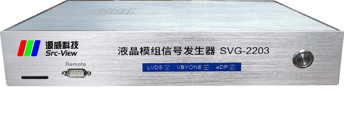
A 3-in-1 LCM pattern test instrument — one unit covering TV, monitor and notebook production lines
Up to 16-lane V-by-One (4096×2160@120Hz), 4-channel LVDS (1920×1080@120Hz), 8-lane eDP (up to 5.4Gbps, 2560×1440@240Hz) — one instrument handles all three interface types.
I2C-based VCOM voltage adjustment; the control box offers +5 / -5 / +1 / -1 four-key fine-tuning, and the "Save" key writes the value to the panel T-CON board memory in one step.
All output signals have protection circuits; panel power and backlight power feature configurable over-voltage, under-voltage, over-current and no-load protection, preventing damage to the instrument and the panel under test.
The standard RMT-220 external control box sits separately from the main unit for flexible placement on the line; dedicated EDID-read and backlight-adjustment keys; frequently used keys are mechanical keys rated for millions of presses.
96+ built-in common test patterns, continuously updated per user requests; unlimited external images via SD card; up to 32 patterns per module parameter set, with auto-play and per-image duration settings.
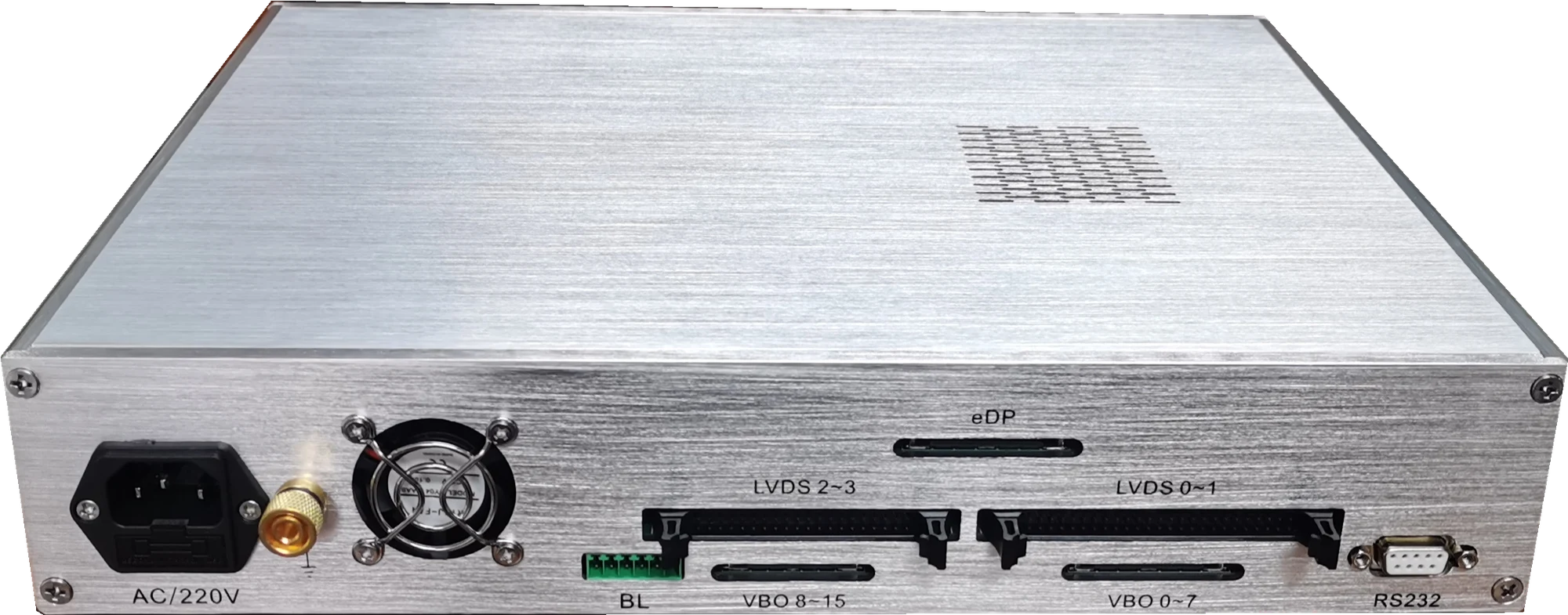
Ready instantly at power-on — no boot wait. Multiple module parameter sets can be preset; switching lines or panels means just switching a parameter number. The RS-232 port supports fixture travel switches — press down to turn on the signal, lift to turn it off; serial protocol customizable.
Detailed electrical and functional parameters for all kinds of LCM pattern testing on production lines
| V-by-One Signal | 1 / 2 / 4 / 8 / 16 Lane Division 1 / 2 / 4 8bit / 10bit Up to 4096×2160@120Hz |
|---|---|
| LVDS Signal | Single / Dual / Quad Channel Division 1 / 2 / 4 6bit / 8bit / 10bit JEIDA / VESA Up to 1920×1080@120Hz |
| eDP Signal | 1 / 2 / 4 / 8 Lane 1.62 / 2.7 / 5.4Gbps Up to 4096×2160@120Hz, 2560×1440@240Hz |
| Flicker Adjustment | I2C-based VCOM voltage adjustment (customer provides the I2C protocol for VCOM adjustment); the VCOM value can be written to the panel’s non-volatile memory |
| Power Signals | T-CON power LVDSVCC: 3.3V–13.5V output; backlight power BLVCC: 3.3V–24V output; max current 4A with current measurement (10mA accuracy); configurable over-voltage / under-voltage / over-current / no-load protection |
| Backlight Signals | BL_VCC (backlight power), BL_ADJ (PWM backlight adjustment), BL_ONOFF (backlight on/off); Dout1–Dout4 digital outputs, logic level 0–3.3V |
| Power Sequencing | Controlled items: LVDSVCC, BLVCC, LVDS / V-by-One signals, control outputs; interval 5mS–500mS, accuracy 5mS |
| Storage | SD card (FAT32, max 32GB, 16GB included) stores module parameter files and test images; up to 32 test patterns per module parameter set |
| Unit Specifications | Dimensions 350 × 280 × 75 mm; weight approx. 2.8 kg (with packaging); power AC 220V (200–240V) 50/60Hz; operating temperature 0°C to +40°C |
| Operation | Split-type RMT-220 control box (standard, connected via DB15 cable); testing requires just 3 buttons — signal on/off, previous, next; plus dedicated keys for EDID read, backlight adjustment, VCOM fine-tuning and save |
| Standard Accessories | RMT-220 control box, 16GB SD card, national-standard 3-pin power cord, male-to-male DB15 cable, 8762-V1 LVDS adapter board (with 50-wire ribbon), 51PIN / 41PIN V-by-One adapter boards and short cables |
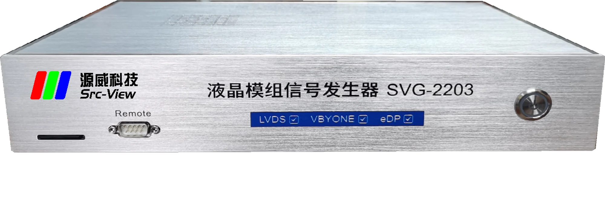
Main unit front panel, rear panel and RMT-220 control box layout at a glance
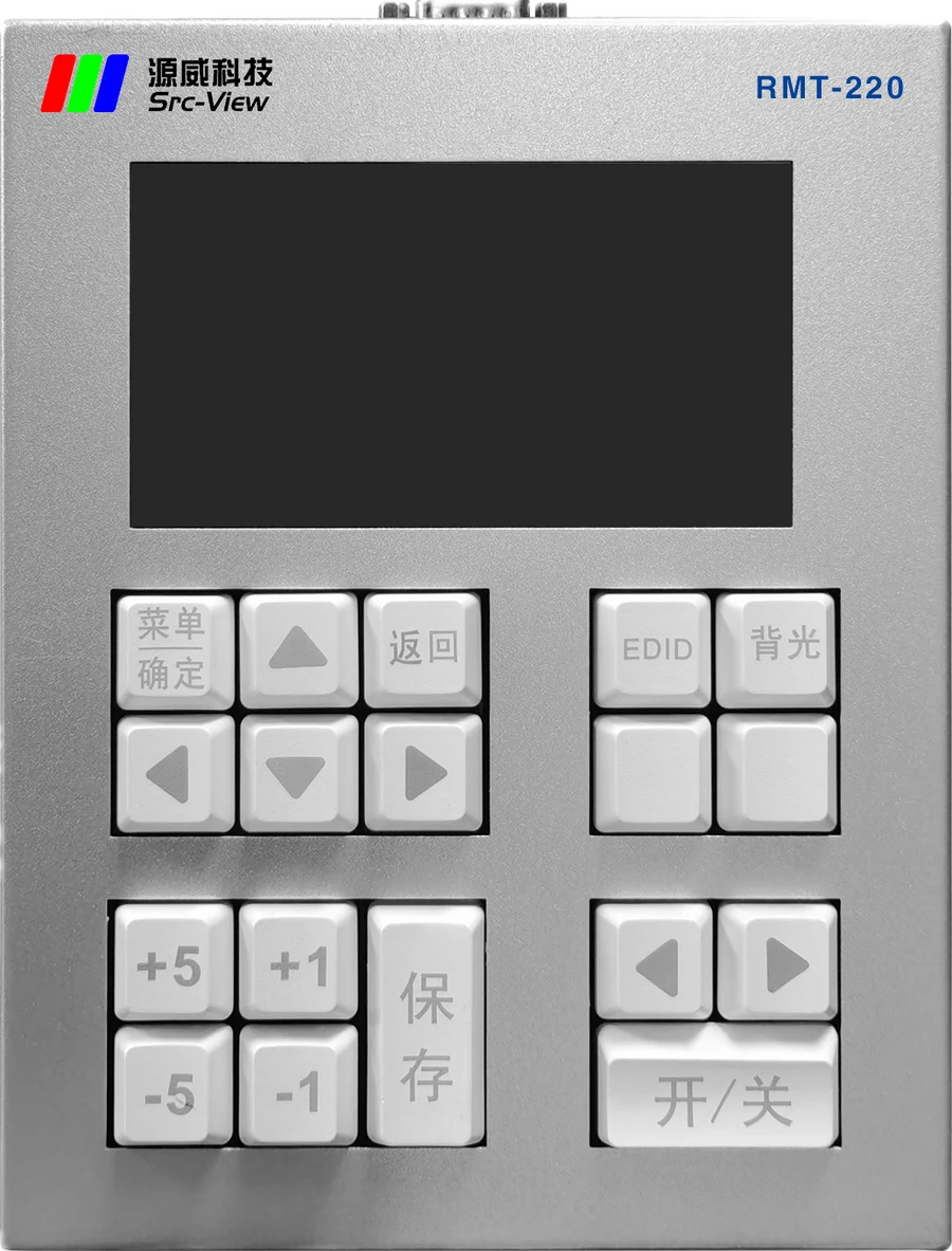
Connects to the main unit via DB15 cable, with its own display and parameter menu. The "On/Off" key controls the signal, "◀" "▶" keys switch test patterns; +5 / -5 / +1 / -1 keys fine-tune VCOM flicker, and the "Save" key writes the value; dedicated keys for EDID read and backlight adjustment. Frequently used keys are mechanical keys rated for millions of presses — built to last.
Complete pattern testing in a few simple steps
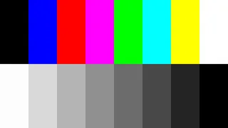
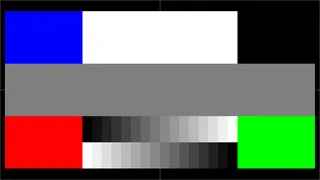
Covering grayscale, color bar, checkerboard, flicker, crosstalk and other common production-line test screens
Continuously updated per user requests, ready at power-on
Just place them in the SD card "BMP" folder
Combine test screens as needed
Per-image duration set independently, 0.5S–20S
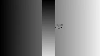
Grayscale background + vertical scrolling bar



























A full comparison of pattern-testing solutions for LCM production lines — professional instruments win across the board
| Item | SVG-2203 Professional Signal Generator | Ordinary Motherboard |
|---|---|---|
| Versatility | ✓Purpose-built for LCM and T-CON production-line pattern testing — one instrument compatible with LVDS / V-by-One / eDP panels | ✗One motherboard only drives its matching panel — changing glass means changing the board |
| Reliability | ✓All interface signals have protection circuits; T-CON power features over-voltage, under-voltage, over-current and no-load protection | ✗No protection — easily damaged |
| Efficiency | ✓Instant on at power-up, highly efficient | ✗Must wait for the motherboard to fully boot; some boot very slowly |
| Operability | ✓Signal on/off and pattern switching with just 3 buttons | ✗Must switch to the USB channel via remote or buttons first, then control USB image playback |
| Cost-Effectiveness | ✓Designed service life of 5–10 years — better long-term value | ✗Frequent damage or even scrapping — higher overall cost |
| Special Requirements | ✓Independently developed — customization available for special panel-inspection processes | ✗Cannot be met |
| Industry Trend | ✓Major brand LCM manufacturers all use professional instruments for pattern testing | — |
| Success Stories | ✓Wistron, Innolux, AUO, Panda, BOE, TCL CSOT | — |
The Common Choice of Many Leading LCM Manufacturers






Quick ways to locate pattern-testing issues
The SVG-2203 is discontinued; the replacement is SVG-2401. Existing users needing manuals, spare parts or technical support are welcome to contact us anytime.
A high-tech enterprise dedicated to R&D and production of test equipment and system products — a professional test equipment provider and service partner for electronics manufacturers.