
16-Lane V-by-One | 4-Channel LVDS | 99 Module Parameter Sets
The AG-5119 is an image signal generator for LCD panel and T-CON board testing, supporting up to 16-lane V-by-One output plus 4-channel LVDS compatibility. It stores 99 module parameter sets with up to 32 test patterns each, supports external images via SD card and OLED display, and programmable 3.3–12V panel power; output interfaces feature quadruple protection (over-voltage / over-current / under-voltage / no-load).
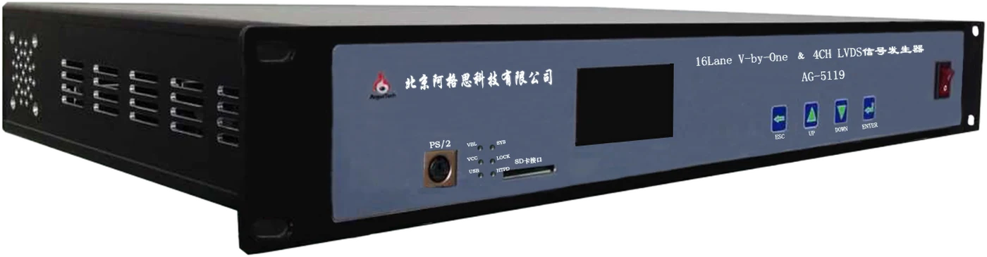
A classic model for LCD panel and T-CON board production testing
1 / 2 / 4 / 8 / 16 lanes selectable, Section 1 / 2 / 4 division, 8-bit / 10-bit depth, max resolution 4096×4096 — covering large-size TV panel and T-CON board testing.
Single / dual / quad-channel LVDS output, 6-bit / 8-bit / 10-bit, JEIDA / VESA formats, pixel clock 150 / 300 / 600MHz — one machine covers both interface types.
3.3V–12V power output is freely programmable, max 1.5A, current measurement accuracy 5mA; configurable quadruple protection (over-voltage / under-voltage / over-current / no-load).
SD card stores module parameters and test images, auto-loading the last module number at power-on; built-in patterns plus external BMPs from SD card, up to 32 patterns per parameter set.
Front panel OLED display + 4 buttons; standard PS/2 numeric keypad, optional PS/2 mouse and IR remote (learnable keys); USB port for host PC connection.
Power-on/off sequencing adjustable 5mS–500mS with 5mS accuracy; the IIC interface supports EDID download, verification and learning — meeting T-CON board programming and verification needs.
Detailed Electrical and Functional Parameters
| V-by-One Output | 1 / 2 / 4 / 8 / 16 LaneSection 1 / 2 / 48bit / 10bitJEIDAMax resolution 4096×4096 |
|---|---|
| LVDS Output | Single / Dual / Quad ChannelSection 1 / 2 / 46bit / 8bit / 10bitJEIDA / VESAPixel clock 150 / 300 / 600MHzMax resolution 4096×4096 |
| Control Outputs | Dout1–Dout4, 2D/3D, LR (3D left/right eye sync signal), BL_EN, DBL_EN, PWM backlight adjustment signal, logic level 0–3.3V; plus 2 function-pin input channels |
| Power Outputs | T-CON power LVDSVCC and backlight power BLVCC: programmable 3.3V–12V output, max 1.5A, current measurement (5mA accuracy); configurable over-voltage / under-voltage / over-current / no-load protection (BLVCC is for T-CON automated test systems, not for pattern testing) |
| EDID Functions | IIC interface, supporting EDID download, verification and learning |
| Test Patterns | 24+ built-in test patterns; external BMP images from the SD card root "ExterImg" folder; up to 32 test patterns per module parameter set; auto / manual switching with editable auto-switch intervals; CustomRGB custom solid-color patterns supported |
| Storage | SD card (FAT32, max 8GB) stores module parameter files and test images; 99 preset module parameter sets (No. 0–98), auto-loading the last-used module number at each power-on |
| Human-Machine Interface | Front panel OLED display + 4 buttons (ESC / UP / DOWN / ENTER); PS/2 numeric keypad (standard) or PS/2 mouse (optional) — left button next, right button previous, middle button signal on/off; IR remote (optional, three learnable keys); USB communication port for host PC |
| Power Sequencing | Controlled items: LVDSVCC, BLVCC, LVDS or V-by-One signals, control outputs; interval 5mS–500mS, accuracy 5mS |
| Unit Specifications | Main unit 400 × 280 × 65 mm (W × D × H), approx. 2 kg; input AC220V 50/60Hz (AC200–240V); guaranteed spec temperature +5°C to +35°C, humidity 20%–80% RH (non-condensing) |
| Standard Configuration | Main unit, Innolux & LG V-by-One adapter boards, TCL CSOT V-by-One adapter board, LVDS adapter board, LVDS cables, PS/2 numeric keypad, 220V power cord; optional: 8G SD card, PS/2 mouse, remote control |
Front and Rear Interface Layout at a Glance

The OLED display shows module number, resolution, channel count, signal format and supply voltage in real time; ESC / UP / DOWN / ENTER buttons handle parameter selection and confirmation; the PS/2 port connects a numeric keypad or mouse; the SD card slot loads module parameter files and test images; the power switch on the right has an indicator.
24+ built-in common test patterns, plus external BMP and custom solid-color images via SD card
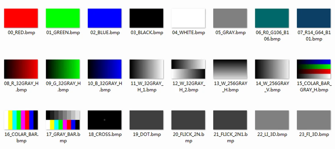
24 built-in common test patterns including grayscale, color bars, solids, checkerboard, windows and pattern-test screens; external test patterns placed in the SD card root "ExterImg" folder are directly callable, up to 32 patterns per module parameter set; auto-play (with independently editable switch intervals per image) and CustomRGB custom solid-color patterns supported — meeting module aging, image inspection and other line testing needs.
The AG-5119 is discontinued; recommended replacement: 209-VL; also available: 169-VL or SVG-2401. Existing users needing manuals, spare parts or technical support are welcome to contact us anytime.
A high-tech enterprise dedicated to R&D and production of test equipment and system products — a professional test equipment provider and service partner for electronics manufacturers.