
16-Lane V-by-One · 4K@120Hz | 4-Channel LVDS · 1080P@120Hz
Developed for TV LCM and T-CON board production testing. Output interfaces feature quadruple protection (over-voltage / over-current / under-voltage / no-load); the whole test requires only 3 buttons — simple, easy, stable and reliable.
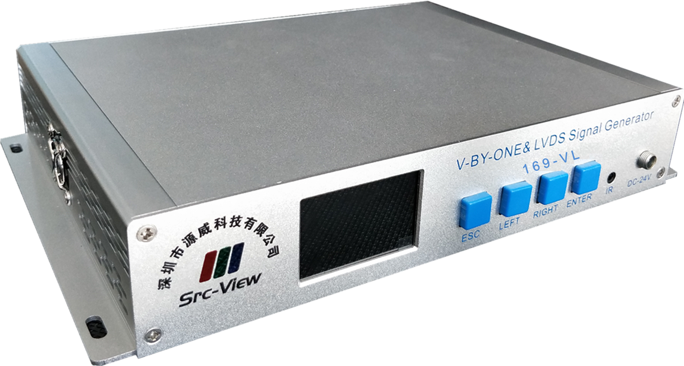
A professional LCM pattern test instrument — full-featured, well-protected and easy to operate
Up to 16-lane V-by-One (3840×2160/120Hz) or 4-channel LVDS (1920×1080/120Hz) — one instrument covers both mainstream interfaces.
All output signals have protection circuits; panel power features configurable over-voltage, under-voltage, over-current and no-load protection, preventing damage to the instrument and the panel under test.
48+ built-in common test patterns (including 3 dynamic scrolling screens); unlimited external images via SD card; up to 16 patterns per module parameter set.
Ready instantly at power-on — enters test mode immediately; 99 preset module parameter sets, so switching lines or panels means just switching a parameter number.
Three control modules supported: remote control (optional), numeric keypad (default), mouse (optional); signal on/off and pattern switching need only 3 buttons.
Supports fixture travel switches — press down to turn on the signal, lift to turn it off; test screens can auto-switch with independent per-image duration.
Detailed electrical and functional parameters for all kinds of production-line pattern testing
| V-by-One Signal | 1 / 2 / 4 / 8 / 16 Lane Division 1 / 2 / 4 8bit / 10bit JEIDA |
|---|---|
| LVDS Signal | Single / Dual / Quad Channel Division 1 / 2 / 4 6 / 8 / 10bit JEIDA / VESA Supports one-to-two (two LVDS panels connected at once) |
| Control Signals | 4-channel configurable logic-level outputs (Dout1–Dout4, BL_ADJ (PWM), BL_ONOFF, 0–3.3V) |
| Power Signals | 3.3V–12V output; max current 2.5A with current measurement (5mA accuracy); configurable over-voltage / under-voltage / over-current / no-load protection |
| Backlight Signals | BL_VCC (backlight power), BL_ADJ (backlight adjustment), BL_ONOFF (backlight on/off); 3.3V–12V / max 2.5A, also with current measurement and quadruple protection |
| Power Sequencing | Controlled items: LVDS VCC, BL VCC, LVDS or V-by-One signals, control outputs; interval 5mS–500mS, accuracy 5mS |
| Storage | Built-in SD card (FAT32, max 32GB) stores module parameter files and test images; up to 99 module parameter sets |
| Unit Specifications | Dimensions 275 × 180 × 50 mm; weight approx. 1.08 kg; power DC 24V; operating temperature 0°C to +40°C |
| Operation | Remote control (optional) / numeric keypad (default) / mouse (optional); just 3 operation buttons: signal on/off, next, previous |
Front-panel operation area and rear-panel signal output area layout at a glance
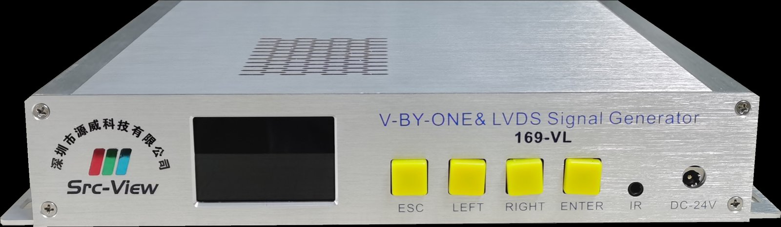
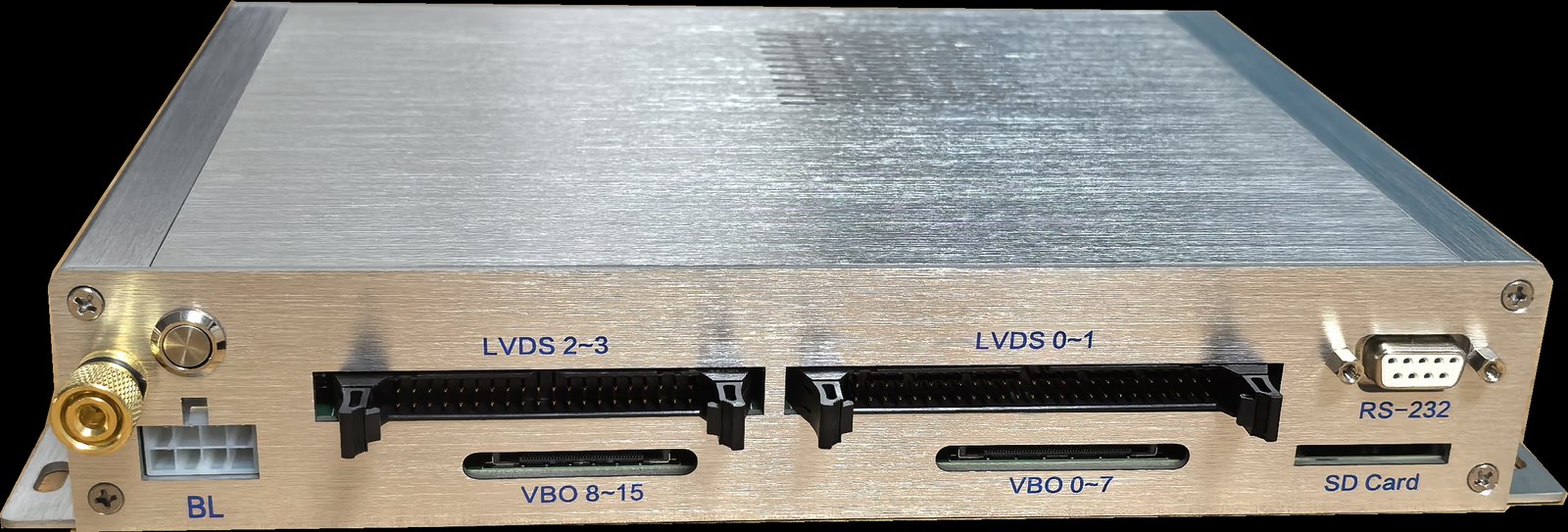

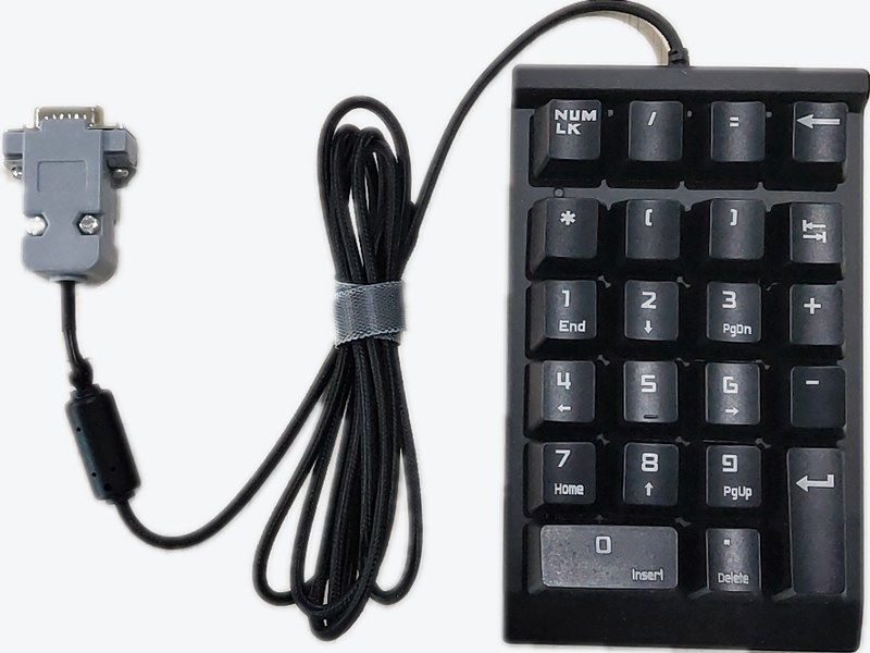
Connects via the RS-232 control port; "0" and "." switch test patterns, Enter controls the signal on/off; a remote control or mouse is optionally available, and a PC with host software can edit module parameters.
Complete pattern testing in a few simple steps
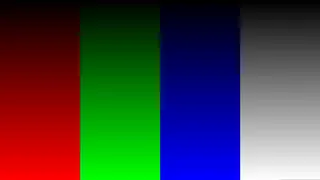
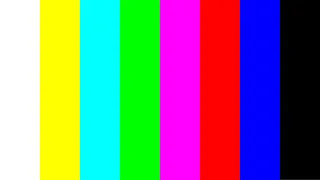
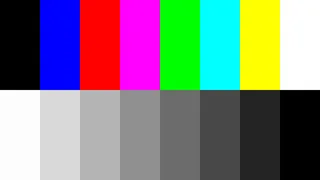
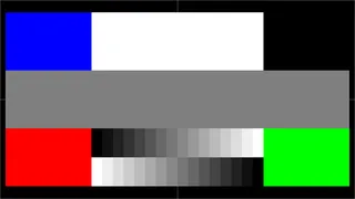
Covering grayscale, color bar, checkerboard, flicker, crosstalk and other common production-line test screens
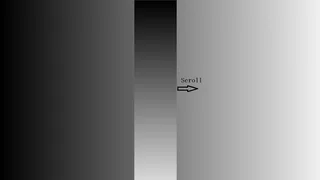
Including 3 dynamic scrolling screens, ready at power-on
Just place them in the SD card "Test Patterns" folder
Combine test screens as needed
Per-image duration set independently
Grayscale background + vertical scrolling bar



















A full comparison of pattern-testing solutions for LCM production lines — professional instruments win across the board
| Item | 169-VL Professional Signal Generator | Ordinary TV Motherboard |
|---|---|---|
| Versatility | ✓Purpose-built for LCM production-line pattern testing, compatible with all LVDS and V-by-One panels | ✗One TV board only drives its matching panel — changing glass means changing the board |
| Reliability | ✓All interface signals have protection circuits; T-CON power features over-voltage, under-voltage, over-current and no-load protection | ✗No protection — easily damaged |
| Efficiency | ✓Instant on at power-up, highly efficient | ✗Must wait for the TV board to fully boot; some boot very slowly |
| Operability | ✓Signal on/off and pattern switching with just 3 buttons | ✗Must switch to the USB channel via remote first, then play USB images |
| Cost-Effectiveness | ✓Designed service life of 5–10 years — better long-term value | ✗Frequent damage or even scrapping — higher overall cost |
| Special Requirements | ✓Independently developed — customization available for special panel-inspection processes | ✗Cannot be met |
| Industry Trend | ✓Major brand LCM manufacturers all use professional instruments for pattern testing | — |
| Success Stories | ✓Skyworth, Changhong, Innolux, AUO, Panda, BOE, TCL CSOT | — |
The Common Choice of Many Leading LCM Manufacturers







Quick ways to locate pattern-testing issues
Request detailed manuals, custom panel-inspection solutions, or discuss cooperation — you are welcome anytime.
A high-tech enterprise dedicated to R&D and production of test equipment and system products — a professional test equipment provider and service partner for electronics manufacturers.
